It is very difficult to design a plate heat performance chart without the use of the manufacturer’s software that provides the necessary correlation between:
1. The flow rate on both the primary and secondary circuits
2. Details of the fluid being used on both the primary and secondary circuits
3. The desired temperature on both the flow and returns on the primary and secondary circuits
4. The KW required
5. The pressure drop on both the primary and secondary circuits
6. The over sizing factor of the design
7. The fouling factor
8. The most suitable plate , gasket configuration and frame to use for the application
9. The connection type and size
10. The foot print and dimensions
Most plate heat exchanger technical designs and quotations can be provided if the information shown in points 1, 2 and 3 shown above are e mailed to our technical office at [email protected].
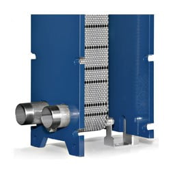
Once the design is checked and accepted by the customer and an order is placed your plate heat exchanger will be assembled and tested in our Cheshire warehouse usually as shown below.
TYPICAL PLATE HEAT EXCHANGER ASSEMBLY PROCEDURE
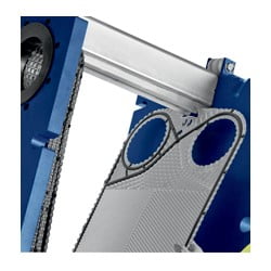
- The plate heat exchanger frame and connections are assembled and the plates start to be put in place.
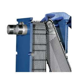
2. Each plate in the plate pack is individually inserted into the frame in the correct order as per the final duty design.
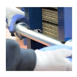
3.Once the plate pack is inserted the tie bars are put in place.
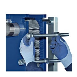
4. Once the tie bars are in place they are tightened pulling the two heavy frame plates together to the correct internal distance by using the required torque setting.
5. When the plates are correctly torqued up a visual inspection is made and a hydraulic test is completed.
6. The plate heat exchanger is then made ready for despatching to site.